
Datasheet


TLE4309
Datasheet 9 Rev. 1.0, 2007-03-20
Application Note: Thermal Considerations
1)
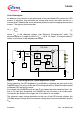
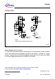
By describing an example, this section shows how the power dissipation and the needed
thermal resistance can be estimated.
For a typical application circuit as shown in Figure 1, the following parameters shall
apply:
• Number of LEDs in series: 3
• LED current desired:
I
F
= 260 mA
• LED minimum forward voltage:
V
F,MIN
= 3.0 V
• LED maximum forward voltage:
V
F,MAX
= 3.4 V
• Supply minimum DC voltage:
V
I,MIN
= 11.0 V
• Supply maximum DC voltage:
V
I,MAX
= 13.0 V
• Maximum ambient temperature:
T
a,max
= 85 °C
1. Selecting the reference resistor:
The reference resistor
R
REF
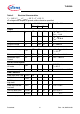
can be selected by using the formular on page 2 or by taking
the value from the typical performance graph “Output Current versus Reference
Resistor” on Page 7. In order to obtain a LED forward current of
I
F
= 260 mA, the graph
shows an reference resistor of
R
REF
= 0.68 Ω.
2. Verifying the minimum supply voltage:
In order to be able to drive the LEDs with a constant current, the minimum supply voltage
needed is:
V
I,MIN
= V
F,MAX,total
+ V
dr
+ V
REF
whereas V
F,MAX,total
is the maximum forward voltage sum of the LEDs connected in
series,
V
dr
the dropout voltage and V
REF
the reference voltage.
Since the power dissipation is low at a small voltage drop accross the regulator,
V
dr
= 0.35 V is assumed. The maximum reference voltags is V
REF
= 185mV. Therefore,
a minimum supply voltage of 11 V is sufficient for the example given above.
3. Determining the minimum and maximum LED forward current:
The TLE4309 has an accuracy of < 4 %. With a reference resistor of
R
REF
=0.68Ω, the
output current
I
Q
will be between 251 mA and 272 mA.
1) This information is given as a hint for the implementation of the device only and shall not be regarded as a
description or warranty of a certain functionality, condition or quality of the device.