
Datasheet
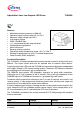


TLE4309
Datasheet 5 Rev. 1.0, 2007-03-20
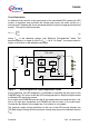
Note: Within the functional range the IC operates as described in the circuit description.
The electrical characteristics are specified within the conditions given in the
related electrical characteristics table
.
Table 3 Operating Range
Parameter Symbol Limit Values Unit Remarks
Min. Max.
Input voltage
V
I
4.5 24 V –
PWM / ENABLE voltage
V
PWM
024V–
Junction temperature
T
j
-40 150 °C–
Reference resistor
R
REF
01.8Ω –
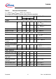
Table 4 Thermal Resistance
Parameter Symbol Typical
Limit Values
Unit Remarks
Junction ambient
R
thja
78 K/W Footprint only
1)
1) Worst case regarding peak temperature; mounted on PCB FR4, 80 × 80 × 1.5 mm
3
, 35 µm Cu,
horizontal position, zero airflow.
52 K/W 300mm
2
heat sink area
1)
39 K/W 600mm
2
heat sink area
1)
Junction case R
thjc
3K/W–