
Datasheet


Datasheet 10 Rev. 1.0, 2007-03-20
TLE4309
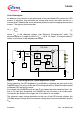
4. Calculating the maximum power dissipation:
For calculating the maximum power dissipation, the minimum forward voltage sum of the
LEDs connected in series
V
F,MIN,total
(=No.ofLEDs*V
F,MIN
) , the maximum supply
voltage
V
I,MAX
, the IC current consumption I
q,MAX
, as well as the the maximum output
current
I
Q,MAX
needs to be considered. Hence, the maximum power dissipation P
D,MAX
calculates:
P
D,MAX
= (V
I,MAX
- V
F,MIN,total
)*I
Q,MAX
+ V
I,MAX
* I
q,MAX
With assuming a maximum current consumption of 15 mA @ I
Q
= 260 mA, the
maximum power dissipation for the example is 1.28 W.
5. Thermal Resistance needed:
The thermal resistance from junction to ambient
R
th,j-a
calculates:
R
th,j-a
= (T
j,max
- T
a,max
) / P
D,MAX
With allowing a junction temperature of 150 °C, the R
th,j-a
needed in our example would
be 50 K/W.
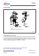
In case some copper area on the PCB is used as a heat sink, the area needed is
approximately 6 cm
2
(board in horizontal position, no airflow). If the area is not available,
several via holes to the GND-layer or to a heatsink area on the PCB backside help to
distribute the heat.
For additional information on the thermal resistance see Infineon’ s special subject book
“Thermal Resistance - Theory and Practice” including extended package information.