
Datasheet


TLE 4299
Datasheet 15 Rev. 1.1, 2007-10-17
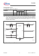
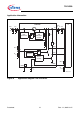
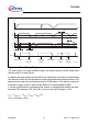
Figure 8 Reset Timing Diagram
The reset output is an open collector output. An external pull-up can be added with a
resistor value of at least 5.6 kΩ.
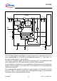
In addition the reset switching threshold can be adjusted by an external voltage divider.
The feature is useful for microprocessors which guarantee safe operation down to volt-
ages below the internally set reset threshold of 3.10V typical. If the internal used reset
threshold of typical 3.10V is used, the pin RADJ has to beconnected to GND.
If a lower reset threshold is required by the system, a voltage divider defines the reset
threshold VRth between 2.5V and 3.10V as long as the Input Voltage V
I
>4.4V
V
Rth
= V
RADJ TH
* (R
ADJ1
+ R
ADJ2
) / R
ADJ2
(3)
V
RADJ TH
is typical 1.36 V.
AED03107
Thermal
t
d
Power-on-Reset Voltage Dip Secondary Overload
at OutputSpike
t
V
ST
V
RO, SAT
RT
V
t
RR
<
RR
t
at Input
Undervoltage
Shutdown
V
V
RO
D
V
t
t
t
t
Q
V
V
I
V
DT
d
d
I
C
D
D
=