
Datasheet

Data Sheet 8 Rev. 1.7, 2007-03-20
TLE 4290
Application Information
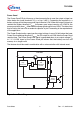
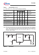
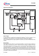
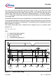
Figure 4 Application Diagram
Input, Output
An input capacitor is necessary for damping line influences. A resistor of approx. 1 Ω in
series with
C
I
, can damp the LC of the input inductivity and the input capacitor.
The TLE 4290 requires an output capacitor of at least 22 μF with an ESR below 5 Ω for
stability.
Power Good
The Power Good pin informs e.g. the micro-controller in case the output voltage has
fallen below a threshold of typ. 3.65 V. When the battery voltage is supplied the Power
Good signal indicates a loss of memory due to missing power. After the Memory Good
switching threshold is reached the Power Good output remains low for the Power Good
delay time. This time can be set by the user with an external capacitor at pin D according
to the requirements of the application, e.g. the time until the microcontroller is initialized
and ready to receive any information.
AES02822
Current
and
Saturation
Control
Band-
Gap-
Reference
TLE 4290
Power
Good
Control
2
5
I
4
C
I
1
C
I
2
V
BAT
C
D
47 nF
GND
R
PG
5 k
22
µF
µ-Controller
V
CC
NMI /
PORT
Internal
Reset
D
PG
Q
100
nF
C
Q2
C
Q1
1