
Datasheet

TLE 4290
Data Sheet 7 Rev. 1.7, 2007-03-20
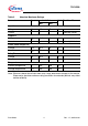
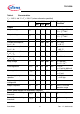
Note: The listed characteristics are ensured over the operating range of the integrated
circuit. Typical characteristics specify mean values expected over the production
spread. If not otherwise specified, typical characteristics apply at
T
a
= 25 °C and
the given supply voltage.
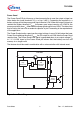
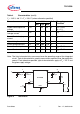
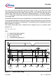
Figure 3 Test Circuit
Power Good output low
voltage
V
PGL
–0.20.4VR
PG
≥ 5 kΩ;
V
Q
> 1 V
Power Good output
leakage current
I
PGH
–02μA V
PG
> 4.5 V
Power Good charging
current
I
D,c
369μA V
D
= 1 V
Upper timing threshold
V
DU
1.5 1.8 2.2 V –
Lower timing threshold
V
DL
0.60 0.85 1.10 V –
Power Good delay time
t
rd
10 16 22 ms C
D
= 47 nF
Power Good reaction time
t
rr
0.2 0.5 2.0 μs C
D
= 47 nF
1) Measured when the output voltage V
Q
has dropped 100 mV from the nominal value obtained at V
I
= 13.5 V.
Table 4 Characteristics (cont’d)
V
I
= 13.5 V; -40 °C < T
j
< 150 °C (unless otherwise specified)
Parameter Symbol Limit Values Unit Measuring
Condition
Min. Typ. Max.
AES02824
TLE 4290
5
2
GND
I
D
C
I2
100 nF
C
I1
1000 µF
C
D
47 nF
I
D,C
I
I
V
I
I
Q
R
PG
5 k
V
Q
I
GND
V
PG
C
Q
22 µF
Q
PG
I
D
4
1