
Datasheet

Data Sheet 6 Rev. 1.7, 2007-03-20
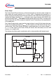
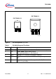
TLE 4290
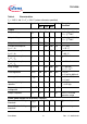
Table 4 Characteristics
V
I
= 13.5 V; -40 °C < T
j
< 150 °C (unless otherwise specified)
Parameter Symbol Limit Values Unit Measuring
Condition
Min. Typ. Max.
Output
Output voltage V
Q
4.9 5.0 5.1 V 5 mA < I
Q
< 400 mA;
6 V <
V
I
< 28 V
Output voltage
V
Q
4.9 5.0 5.1 V 5 mA < I
Q
< 200 mA;
6 V <
V
I
< 40 V
Output current limitation
I
Q
450 700 – mA
1)
Current consumption;
I
q
= I
I
- I
Q
I
q
– 200 230 μA I
Q
= 1 mA;
T
j
= 25 °C
Current consumption;
I
q
= I
I
- I
Q
I
q
– 200 255 μA I
Q
= 1 mA;
T
j
≤ 85 °C
Current consumption;
I
q
= I
I
- I
Q
I
q
–512mAI
Q
= 250 mA
Current consumption;
I
q
= I
I
- I
Q
I
q
–1225mAI
Q
= 400 mA
Drop voltage
V
dr
– 250 500 mV I
Q
= 300 mA
V
dr
= V
I
- V
Q
1)
Load regulation ΔV
Q,lo
-30 15 30 mV V
I
= 6 V;
I
Q
= 5 mA to 400 mA
Line regulation Δ
V
Q,li
-15 5 15 mV V
l
= 8 V to 32 V;
I
Q
= 5 mA
Power supply ripple
rejection
PSRR –60–dBf
r
= 100 Hz;
V
r
= 0.5 Vpp
Temperature output
voltage drift
d
V
Q
/dT –0.5–mV/K–
Output Capacitor
C
Q
22 – – μFESR < 5 Ω in the
operation range
Power Good Output PG and Delay Timing D
Power Good switching
threshold
V
Q,pgt-i
4.45 4.65 4.80 V V
Q
increasing
Power Good switching
threshold
V
Q,pgt-d
3.50 3.65 3.80 V V
Q
decreasing