
Datasheet

TLE 4276
Data Sheet 3 Rev. 2.7, 2007-10-23
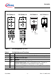
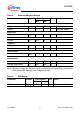
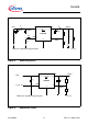
Figure 1 Pin Configuration (top view)
Table 1 Pin Definitions and Functions
Pin No. Symbol Function
1I Input; block to ground directly at the IC with a ceramic capacitor.
2INHInhibit; low-active input.
3GNDGround
4N.C.
VA
Not connected for V50, V85, V10
Voltage Adjust Input; only for adjustable version. Connect an
external voltage divider to determine the output voltage.
5QOutput; block to GND with a ≥ 22 µF capacitor, ESR ≤ 3 Ω at 10 kHz
Heatsink Connect to GND.
Q
Ι
GND
N.C.
INH
1
5
AEP02041
(VA)
GND
Ι
INH
(VA)
AEP02042
N.C.
Q
1
5
AEP02560
15
INH
Ι
N.C.
Q
(VA)
GND
1
5
GND
INH
Ι
AEP02043
N.C.
(VA)
Q
PG-TO220-5-11 PG-TO220-5-12 PG-TO263-5-1 PG-TO252-5-11