
Datasheet
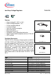
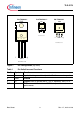
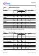
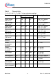

Table 2 Absolute Maximum Ratings
T
j
= -40 to 150 °C
Parameter Symbol Limit Values Unit Test Condition
Min. Max.
Input
Voltage V
I
-42 45 V –
Current
I
I
– – – Internally limited
Output
Voltage V
Q
-1.0 40 V –
Current
I
Q
– – – Internally limited
Ground
Current I
GND
– 100 mA –
Temperature
Junction temperature T
j
– 150 °C –
Storage temperature
T
stg
-50 150 °C –
Table 3 Operating Range
Parameter Symbol Limit Values Unit Remarks
Min. Max.
Input voltage; V50, DV50,
GV50
V
I
5.5 40 V –
Input voltage, V85, GV85
V
I
9.0 40 V –
Input voltage, V10, GV10
V
I
10.5 40 V –
Junction temperature
T
j
-40 150 °C –
Thermal Resistance
Junction ambient R
thja
– 65 K/W TO220
1)
Junction ambient R
thja
– 78 K/W TO252
1)
1) Worst case; regarding peak temperature, zero airflow mounted on PCB 80 × 80 × 1.5 mm
3
, 300 mm
2
heat sink
area.
Junction ambient R
thja
– 52 K/W TO263
1)
Junction case R
thjc
– 4 K/W –
TLE 4274
Data Sheet 5 Rev. 1.7, 2011-01-20
Note: Maximum ratings are absolute ratings; exceeding any one of these values may
cause irreversible damage to the integrated circuit.