
Datasheet

TLE 4269
Data Sheet 5 Rev. 2.4, 2007-03-20
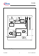
Circuit Description
The control amplifier compares a reference voltage, made highly accurate by resistance
balancing, with a voltage proportional to the output voltage and drives the base of the
series PNP transistor via a buffer. Saturation control as a function of the load current
prevents any over-saturation of the power element.
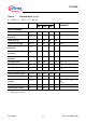
The reset output RO is in high-state if the voltage on the delay capacitor
C
D
is greater or
equal
V
UD
. The delay capacitor C
D
is charged with the current I
D
for output voltages
greater than the reset threshold
V
RT
. If the output voltage gets lower than V
RT
(‘reset
condition’) a fast discharge of the delay capacitor
C
D
sets in and as soon as V
D
gets
lower than
V
LD
the reset output RO is set to low-level.
The time gap for the delay capacitor discharge is the reset reaction time
t
RR
.
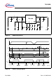
The reset threshold
V
RT
can be decreased via an external voltage divider connected to
the pin RADJ. In this case the reset condition is reached if
V
Q
< V
RT
and
V
RADJ
< V
RAQDJ, TH
. Dimensioning the voltage divider (Figure 5) according to:
V
THRES
= V
RADJ,TH
× (R
ADJ1
+ R
ADJ2
) / R
ADJ2
,(1)
the reset threshold can be decreased down to 3.5 V. If the reset-adjust-option is not
needed the RADJ-pin should be connected to GND causing the reset threshold to go to
its default value (typ. 4.65 V).
A built in comparator compares the signal of the pin SI, normally fed by a voltage divider
from the input voltage, with the reference and gives an early warning on the pin SO. It is
also possible to superwise another voltage e.g. of a second regulator, or to build a
watchdog circuit with few external components.
Application Description
The input capacitor
C
I
is necessary for compensating line influences. Using a resistor of
approx. 1 Ω in series with
C
I
, the oscillating circuit consisting of input inductivity and input
capacitance can be damped. The output capacitor
C
Q
is necessary for the stability of the
regulating circuit. Stability is guaranteed at values ≥ 10 µF and an ESR ≤ 10 Ω within the
operating temperature range. For small tolerances of the reset delay the spread of the
capacitance of the delay capacitor and its temperature coefficient should be noted.