
Datasheet

TLE 4269
Data Sheet 3 Rev. 2.4, 2007-03-20
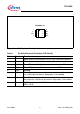
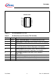
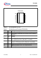
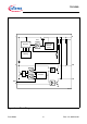
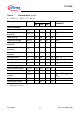
Figure 2 Pin Configuration (top view)
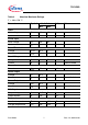
Table 2 Pin Definitions and Functions (TLE 4269 GM)
Pin No. Symbol Function
1RADJReset Threshold Adjust; if not needed connect to GND.
2DReset Delay; to select delay time; connect to GND via capacitor.
3, 4, 5, 6 GND Ground
7ROReset Output; open-collector output, internally connected to Q
via a pull-up resistor of 20 kΩ. Keep open, if not needed.
8SOSense Output; open-collector output, internally connected to Q
via a 20 kΩ pull-up resistor. Keep open, if not needed.
9Q5-V Output; connect to GND with a 10 µF capacitor,
ESR < 10 Ω.
10, 11, 12 GND Ground
13 I Input; block to GND directly at the IC with a ceramic capacitor.
14 SI Sense Input; if not needed connect to Q.
AEP02248
Q
GND
SI
GND
RO
GND
Ι
10
9
GND GND
1
2
3
4
5
GND
6
7SO
14
13
12
11
D
GND
8
RADJ
PG-DSO-14-30