
Datasheet


Data Sheet 5 Rev. 1.0, 2008-04-21
TLE4263-2ES
Pin Configuration
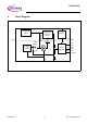
3 Pin Configuration
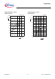
3.1 Pin Assignment
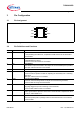
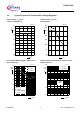
Figure 2 Pin Configuration
3.2 Pin Definitions and Functions
Pin Symbol Function
1I Input
for compensating line influences, a capacitor to GND close to the IC terminals is
recommended
2INH Inhibit
enables/disables the device;
connect to I if the this function is not needed
3RO Reset Output
open-collector output connected to the output via an internal 30kΩ pull-up resistor;
leave open if the this function is not needed
4GND Ground
5D Reset Delay Timing
connect a ceramic capacitor to GND for adjusting the reset delay time / watchdog
trigger time;
leave open if this function is not needed
6RADJ Reset Threshold Adjust
connect an external voltage divider to adjust the reset switching threshold;
connect to GND for using internal threshold
7W Watchdog
rising edge triggered input for monitoring a microcontroller;
connect to GND if this function is not needed
8Q Output
block to ground with a capacitor close to the IC terminals with a capacitance value
C ≥ 22 µF, and an ESR ≤ 3 Ω
PAD – Exposed Pad
attach the exposed pad on package bottom to the heatsink area on circuit board;
connect to GND
4
:
5$'-
'
,
,1+
52
*1'