
Datasheet


Data Sheet 3 Rev. 1.0, 2008-04-21
TLE4263-2ES
Overview
Dimensioning Information on External Components
The input capacitor
C
I
is recommended for compensation of line influences. The output capacitor C
Q
is necessary
for the stability of the control loop. Stability is guaranteed at values ≥ 22 µF and an ESR of ≤ 3 Ω within the
operating temperature range. For small tolerances of the reset delay the capacitance’s spread of the delay
capacitor
C
D
and its temperature coefficient should be taken into consideration.
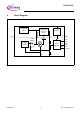
Circuit Description
The control amplifier compares a reference voltage to a voltage that is proportional to the output voltage and drives
the base of the series transistor via a buffer. Saturation control as a function of the load current prevents any
oversaturation of the power element. The component also has a number of internal circuits for protection against:
• Overload
• Overtemperature
• Reverse polarity
In case the externally scaled down output voltage at the reset adjust input falls below 1.35 V, the external reset
delay capacitor
C
D
is discharged by the reset generator. When the voltage of the capacitor reaches the lower
threshold
V
DRL
, a reset signal occurs at the reset output and is held until the upper threshold V
DU
is exceeded. If
the reset threshold input is connected to GND, reset is triggered at an output voltage of typically 4.65 V.