
Datasheet


C505/C505C/C505A/C505CA
Data Sheet 34 12.00
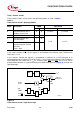
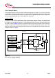
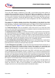
Figure 14
Block Diagram of Baud Rate Generation for the Serial Interface
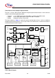
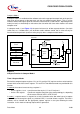
Table 8 below lists the values/formulas for the baud rate calculation of the serial interface with its
dependencies of the control bits BD and SMOD.
Table 8
Serial Interface - Baud Rate Dependencies
Serial Interface
Operating Modes
Active Control Bits Baud Rate Calculation
BD SMOD
Mode 0 (Shift Register) ––
f
OSC
/ 6
Mode 1 (8-bit UART)
Mode 3 (9-bit UART)
0 X Controlled by timer 1 overflow :
(2
SMOD
× timer 1 overflow rate) / 32
1 X Controlled by baud rate generator
(2
SMOD
× f
OSC
) /
(32 × baud rate generator overflow rate)
Mode 2 (9-bit UART) – 0
1
f
OSC
/ 32
f
OSC
/ 16
MCS02733
Rate
f
OSC
(SMOD)
Baud
Clock
PCON.7
2
(SM0/
SM1)
SCON.7
SCON.6
Only one mode
can be selected
ADCON0.7
(BD)
0
1
0
1
Baud
Rate
Generator
(SRELH
SRELL)
Timer 1
Mode 2
Mode 0
Note: The switch configuration shows the reset state.
Mode 3
Mode 1
Overflow
6
÷
÷