
Datasheet


C505/C505C/C505A/C505CA
Data Sheet 31 12.00
Timer 2 Compare Modes
The compare function of a timer/register combination operates as follows : the 16-bit value stored
in a compare or compare/capture register is compared with the contents of the timer register; if the
count value in the timer register matches the stored value, an appropriate output signal is generated
at a corresponding port pin and an interrupt can be generated.
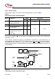
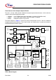
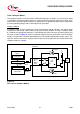
Compare Mode 0
In compare mode 0, upon matching the timer and compare register contents, the output signal
changes from low to high. lt goes back to a low level on timer overflow. As long as compare mode
0 is enabled, the appropriate output pin is controlled by the timer circuit only and writing to the port
will have no effect. Figure 12 shows a functional diagram of a port circuit when used in compare
mode 0. The port latch is directly controlled by the timer overflow and compare match signals. The
input line from the internal bus and the write-to-latch line of the port latch are disconnected when
compare mode 0 is enabled.
Figure 12
Port Latch in Compare Mode 0
MCS02661
Latch
Port
Q
Q
CLK
D
Port
Pin
Read Pin
DD
V
Read Latch
Port Circuit
Internal
Bus
Latch
Write to
Compare Reg.
Compare Register
Circuit
Comparator
Timer Register
Timer Circuit
Compare
Match
S
R
Overflow
Timer
16 Bit
Bit16