
Datasheet


XC164-32
Derivatives
General Device Information
Data Sheet 14 V1.1, 2006-08
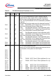
PORT0
P0L.0 -
P0L.7
P0H.0 -
P0H.3
P0H.4 -
P0H.7
67 - 74
4 - 7
75 - 78
IO PORT0 consists of the two 8-bit bidirectional I/O ports P0L
and P0H. Each pin can be programmed for input (output
driver in high-impedance state) or output.
In case of an external bus configuration, PORT0 serves as
the address (A) and address/data (AD) bus in multiplexed
bus modes and as the data (D) bus in demultiplexed bus
modes.
Demultiplexed bus modes:
8-bit data bus: P0H = I/O, P0L = D7 - D0
16-bit data bus: P0H = D15 - D8, P0L = D7 - D0
Multiplexed bus modes:
8-bit data bus: P0H = A15 - A8, P0L = AD7 - AD0
16-bit data bus: P0H = AD15 - AD8, P0L = AD7 - AD0
Note: At the end of an external reset (EA
= 0) PORT0 also
may input configuration values
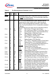
PORT1
P1L.0
P1L.1
P1L.2
P1L.3
P1L.4
P1L.5
P1L.6
P1L.7
P1H
79
80
81
82
83
84
85
86
…
IO
I/O
O
I/O
O
I/O
O
O
I
I/O
PORT1 consists of the two 8-bit bidirectional I/O ports P1L
and P1H. Each pin can be programmed for input (output
driver in high-impedance state) or output.
PORT1 is used as the 16-bit address bus (A) in
demultiplexed bus modes (also after switching from a
demultiplexed to a multiplexed bus mode).
The following PORT1 pins also serve for alt. functions:
CC60 CAPCOM6: Input / Output of Channel 0
COUT60 CAPCOM6: Output of Channel 0
CC61 CAPCOM6: Input / Output of Channel 1
COUT61 CAPCOM6: Output of Channel 1
CC62 CAPCOM6: Input / Output of Channel 2
COUT62 CAPCOM6: Output of Channel 2
COUT63 Output of 10-bit Compare Channel
CTRAP
CAPCOM6: Trap Input
CTRAP
is an input pin with an internal pull-up resistor. A low
level on this pin switches the CAPCOM6 compare outputs to
the logic level defined by software (if enabled).
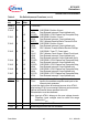
CC22IO CAPCOM2: CC22 Capture Inp./Compare Outp.
…continued…
Table 2 Pin Definitions and Functions (cont’d)
Sym-
bol
Pin
Num.
Input
Outp.
Function