
Datasheet


C161S
Electrical Parameters
Data Sheet 41 V1.0, 2003-11
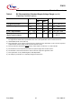
Table 12 Power Consumption C161S (Reduced Supply Voltage Range)
(Operating Conditions apply)
Parameter Symbol Limit Values Unit Test Condition
Min. Max.
Power supply current (active)
with all peripherals active
I
DD3
– 7 +
1.2
× f
CPU
mA RSTIN = V
IL2
f
CPU
in [MHz]
1)
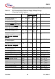
Idle mode supply current
with all peripherals active
I
IDX3
– 1 +
0.4
× f
CPU
mA RSTIN = V
IH1
f
CPU
in [MHz]
1)
Idle mode supply current
with all peripherals deactivated,
PLL off, SDD factor = 32
I
IDO3
2)
– 300 +
30
× f
OSC
µARSTIN = V
IH1
f
OSC
in [MHz]
1)
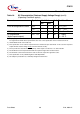
Sleep and Power down mode
supply current with RTC running
I
PDR3
2)
– 100 +
10
× f
OSC
µA V
DD
= V
DDmax
f
OSC
in [MHz]
3)
Sleep and Power down mode
supply current with RTC disabled
I
PDO3
– 30 µA V
DD
= V
DDmax
3)
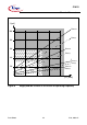
1) The supply current is a function of the operating frequency. This dependency is illustrated in Figure 8.
These parameters are tested at
V
DDmax
and maximum CPU clock with all outputs disconnected and all inputs
at
V
IL
or V
IH
.
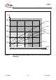
2) This parameter is determined mainly by the current consumed by the oscillator (see Figure 9). This current,
however, is influenced by the external oscillator circuitry (crystal, capacitors). The values given refer to a
typical circuitry and may change in case of a not optimized external oscillator circuitry.
3) This parameter is tested including leakage currents. All inputs (including pins configured as inputs) at 0 V to
0.1 V or at
V
DD
- 0.1 V to V
DD
, V
REF
= 0 V, all outputs (including pins configured as outputs) disconnected.