
Datasheet


&3,
Data Sheet 23 1999-07
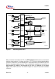
The state of this latch may be used to clock timer T5. The overflows/underflows of timer
T6 can additionally be used to cause a reload from the CAPREL register. The CAPREL
register may capture the contents of timer T5 based on an external signal transition on
the corresponding port pin (CAPIN), and timer T5 may optionally be cleared after the
capture procedure. This allows absolute time differences to be measured or pulse
multiplication to be performed without software overhead.
The capture trigger (timer T5 to CAPREL) may also be generated upon transitions of
GPT1 timer T3’s inputs T3IN and/or T3EUD. This is especially advantageous when T3
operates in Incremental Interface Mode.
Figure 7 Block Diagram of GPT2
MUX
2
n
: 1
f
CPU
T5
Mode
Control
GPT2 Timer T5
2
n
: 1
f
CPU
T6
Mode
Control
GPT2 Timer T6
GPT2 CAPREL
T6OTL
T3
CAPIN
T6OUT
U/D
U/D
Interrupt
Request
Interrupt
Request
Interrupt
Request
Other
Timers
Clear
Capture
CT3
Mcb03999C.vsd