
Datasheet


C161K
C161O
Data Sheet 38 V2.0, 2001-01
AC Characteristics
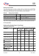
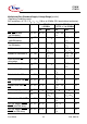
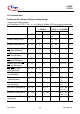
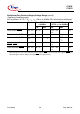
Table 10 External Clock Drive XTAL1 (Standard Supply Voltage Range)
(Operating Conditions apply)
Parameter Symbol Direct Drive
1:1
Prescaler
2:1
Unit
min. max. min. max.
Oscillator period
t
OSC
SR 40 – 20 – ns
High time
1)
1)
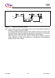
The clock input signal must reach the defined levels V
IL2
and V
IH2
.
t
1
SR 20
2)
2)
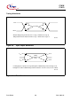
The minimum high and low time refers to a duty cycle of 50%. The maximum operating frequency (f
CPU
) in
direct drive mode depends on the duty cycle of the clock input signal.
– 6 – ns
Low time
1)
t
2
SR 20
2)
– 6 – ns
Rise time
1)
t
3
SR – 10 – 6ns
Fall time
1)
t
4
SR – 10 – 6ns
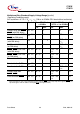
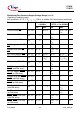
Table 11 External Clock Drive XTAL1 (Reduced Supply Voltage Range)
(Operating Conditions apply)
Parameter Symbol Direct Drive
1:1
Prescaler
2:1
Unit
min. max. min. max.
Oscillator period
t
OSC
SR 50 – 25 – ns
High time
1)
1)
The clock input signal must reach the defined levels V
IL2
and V
IH2
.
t
1
SR 25
2)
2)
The minimum high and low time refers to a duty cycle of 50%. The maximum operating frequency (f
CPU
) in
direct drive mode depends on the duty cycle of the clock input signal.
– 8 – ns
Low time
1)
t
2
SR 25
2)
– 8 – ns
Rise time
1)
t
3
SR – 10 – 6ns
Fall time
1)
t
4
SR – 10 – 6ns