
Datasheet

IRLML0060TRPbF
6 www.irf.com
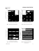
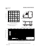
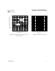
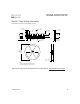
Fig 13. Typical On-Resistance vs. Drain
Current
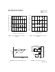
Fig 12. Typical On-Resistance vs. Gate
Voltage
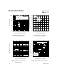
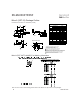
Fig 14b. Gate Charge Test Circuit
Fig 14a. Basic Gate Charge Waveform
Q
G
Q
GS
Q
GD
V
G
Charge
V
GS
D.U.T.
V
DS
I
D
I
G
3mA
V
GS
.3F
50K
.2F
12V
Current Regulator
Same Type as D.U.T.
Current Sampling Resistors
+
-
3 4 5 6 7 8 9 10
V
GS,
Gate -to -Source Voltage (V)
0
100
200
300
400
R
D
S
(
o
n
)
,
D
r
a
i
n
-
t
o
-
S
o
u
r
c
e
O
n
R
e
s
i
s
t
a
n
c
e
(
m
)
I
D
= 2.7A
T
J
= 25°C
T
J
= 125°C
0 2 4 6 8 10 12
I
D
, Drain Current (A)
50
75
100
125
150
R
D
S
(
o
n
)
,
D
r
a
i
n
-
t
o
-
S
o
u
r
c
e
O
n
R
e
s
i
s
t
a
n
c
e
(
m
)
Vgs = 10V
Vgs = 4.5V