
Datasheet


IRL7833/S/LPbF
www.irf.com 5
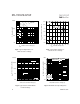
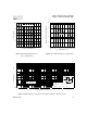
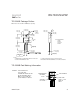
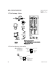
Fig 11. Maximum Effective Transient Thermal Impedance, Junction-to-Case
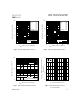
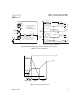
Fig 9. Maximum Drain Current Vs.
Case Temperature
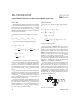
Fig 10. Threshold Voltage Vs. Temperature
25 50 75 100 125 150 175
0
40
80
120
160
I , Drain Current (A)
D
LIMITED BY PACKAGE
T
C
, Case Temperature (°C)
-75 -50 -25 0 25 50 75 100 125 150 175
T
J
, Temperature ( °C )
0.0
0.5
1.0
1.5
2.0
2.5
V
G
S
(
t
h
)
G
a
t
e
t
h
r
e
s
h
o
l
d
V
o
l
t
a
g
e
(
V
)
I
D
= 250µA
0.01
0.1
1
10
0.00001 0.0001 0.001 0.01 0.1 1
Notes:
1. Duty factor D = t / t
2. Peak T = P x Z + T
1 2
J DM thJC C
P
t
t
DM
1
2
t , Rectangular Pulse Duration (sec)
Thermal Response (Z )
1
thJC
0.01
0.02
0.05
0.10
0.20
D = 0.50
SINGLE PULSE
(THERMAL RESPONSE)