
Datasheet


IRFZ24N
6 www.irf.com
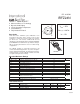
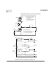
Fig 12a. Unclamped Inductive Test Circuit
V
DS
L
D.U.T.
V
DD
I
AS
t
p
0.01Ω
R
G
+
-
t
p
V
DS
I
AS
V
DD
V
(BR)DSS
10 V
Fig 12b. Unclamped Inductive Waveforms
D.U.T.
V
DS
I
D
I
G
3mA
V
GS
.3µF
50KΩ
.2µF
12V
Current Regulator
Same Type as D.U.T.
Current Sampling Resistors
+
-
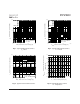
Fig 13b. Gate Charge Test Circuit
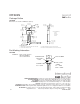
Q
G
Q
GS
Q
GD
V
G
Charge
10 V
Fig 13a. Basic Gate Charge Waveform
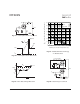
Fig 12c. Maximum Avalanche Energy
Vs. Drain Current
0
20
40
60
80
100
120
140
25 50 75 100 125 150 175
J
E , Single Pulse Avalanche Energy (mJ)
AS
A
Startin
g
T , Junction Temperature
(
°C
)
I
TOP 4.2A
7.2A
BOTTOM 10A
V = 25V
D
DD