
Datasheet


IRF7907PbF
6 www.irf.com
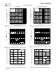
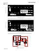
Q1 - Control FET Q2 - Synchronous FET
Typical Characteristics
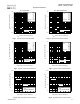
Fig 19. Maximum Drain Current vs. Ambient Temp.
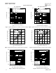
Fig 20. Maximum Drain Current vs. Ambient Temp.
Fig 21. Threshold Voltage vs. Temperature Fig 22. Threshold Voltage vs. Temperature
Fig 23. Maximum Avalanche Energy vs. Drain Current
Fig 24. Maximum Avalanche Energy vs. Drain Current
-75 -50 -25 0 25 50 75 100 125 150
T
J
, Temperature ( °C )
1.0
1.2
1.4
1.6
1.8
2.0
2.2
V
G
S
(
t
h
,
G
a
t
e
t
h
r
e
s
h
o
l
d
V
o
l
t
a
g
e
(
V
)
I
D
= 250µA
25 50 75 100 125 150
Starting T
J
, Junction Temperature (°C)
0
10
20
30
40
50
E
A
S
,
S
i
n
g
l
e
P
u
l
s
e
A
v
a
l
a
n
c
h
e
E
n
e
r
g
y
(
m
J
)
I
D
TOP
3.0A
3.5A
BOTTOM
7.0A
25 50 75 100 125 150
T
J
, Ambient Temperature (°C)
0
2
4
6
8
10
12
I
D
,
D
r
a
i
n
C
u
r
r
e
n
t
(
A
)
-75 -50 -25 0 25 50 75 100 125 150
T
J
, Temperature ( °C )
1.0
1.2
1.4
1.6
1.8
2.0
2.2
V
G
S
(
t
h
,
G
a
t
e
t
h
r
e
s
h
o
l
d
V
o
l
t
a
g
e
(
V
)
I
D
= 250µA
25 50 75 100 125 150
Starting T
J
, Junction Temperature (°C)
0
10
20
30
40
50
60
E
A
S
,
S
i
n
g
l
e
P
u
l
s
e
A
v
a
l
a
n
c
h
e
E
n
e
r
g
y
(
m
J
)
I
D
TOP
3.8A
4.4A
BOTTOM
8.8A
25 50 75 100 125 150
T
J
, Ambient Temperature (°C)
0
2
4
6
8
10
I
D
,
D
r
a
i
n
C
u
r
r
e
n
t
(
A
)