
Datasheet

IRF7425PbF
6 www.irf.com © 2013 International Rectifier Submit Datasheet Feedback October 29, 2013
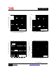
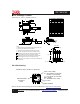
Fig 13. Typical On-Resistance Vs.
Drain Current
Fig 12. Typical On-Resistance Vs.
Gate Voltage
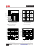
Fig 14b. Gate Charge Test Circuit
Fig 14a. Basic Gate Charge Waveform
Q
G
Q
GS
Q
GD
V
G
Charge
D.U.T.
V
DS
I
D
I
G
-3mA
V
GS
.3μF
50KΩ
.2μF
12V
Current Regulator
Same Type as D.U.T.
Current Sampling Resistors
+
-
1.0 2.0 3.0 4.0 5.0
-V
GS,
Gate -to -Source Voltage (V)
0.005
0.010
0.015
R
D
S
(
o
n
)
,
D
r
a
i
n
-
t
o
-
S
o
u
r
c
e
O
n
R
e
s
i
s
t
a
n
c
e
(
Ω
)
I
D
= -15A
0 102030405060
-I
D
, Drain Current (A)
0.005
0.006
0.007
0.008
0.009
0.010
R
D
S
(
o
n
)
,
D
r
a
i
n
-
t
o
-
S
o
u
r
c
e
O
n
R
e
s
i
s
t
a
n
c
e
(
Ω
)
V
GS
= -2.5V
V
GS
= -4.5V