
Datasheet
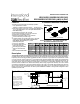


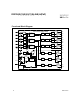

IR2136(2)(3)(5)(6)(7)(8)
(
J&S) & (PbF
)
4 www.irf.com
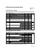
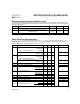
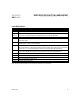
Static Electrical Characteristics cont.
V
BIAS
(V
CC
, V
BS
1,2,3) = 15V unless otherwise specified. The V
IN
, V
TH
and I
IN
parameters are referenced to V
SS
and
are applicable to all six channels (H
S
1,2,3 and L
S
1,2,3). The V
O
and I
O
parameters are referenced to COM and V
S
1,2,3
and are applicable to the respective output leads: H
O1,2,3
and L
O1,2,3.
Symbol Definition Min. Typ. Max. Units Test Conditions
V
CCUV-
V
CC
and V
BS
supply undervoltage IR2136(8) 7.4 8.2 9.0
V
BSUV-
negative going threshold IR21362 8.6 9.4 10.2
IR21363(5)(6)(7) 10.4 10.9 11.4
V
CCUVH
V
CC
and V
BS
supply undervoltage IR2136 0.3 0.7 —
V
BSUVH
lockout hysteresis IR21362 0.5 1.0 —
IR21363(5) — 0.2 —
I
LK
Offset supply leakage current — — 50 V
B1,2,3
=V
S1,2,3=600V
I
QBS
Quiescent V
BS
supply current — 70 120
I
QCC
Quiescent V
CC
supply current — 1.6 2.3 mA
V
IN, CLAMP Input clamp voltage (HIN, LIN, ITRIP and EN)
4.9 5.2 5.5 V I
IN =100µA
I
LIN+
Input bias current (LOUT = HI) IR2136(2)(3)(5) — 200 300 V
LIN = 5V
IR21366(7)(8)
—01
I
LIN-
Input bias current (LOUT = LO) IR2136(2)(3)(5) — 100 220 V
LIN = 0V
IR21366(7)(8)
—01
I
HIN+
Input bias current (HOUT = HI) IR2136(3)(5) — 200 300 V
HIN = 5V
IR21362
— 30 100
IR21366(7)(8)
—01
I
HIN-
Input bias current (HOUT = LO) IR2136(3)(5) — 100 220 V
HIN = 0V
IR21362(6)(7)(8)
—01
I
ITRIP+
“high” ITRIP input bias current — 30 100 V
ITRIP
= 5V
I
ITRIP-
“low” ITRIP input bias current — 0 1 V
ITRIP
= 0V
I
EN+
“high” ENABLE input bias current — 30 100 V
ENABLE
= 5V
I
EN-
“low” ENABLE input bias current — 0 1 V
ENABLE
= 0V
I
RCIN
RCIN input bias current — 0 1 V
RCIN
= 0V or 15V
I
O+
Output high short circuit pulsed current 120 200 — V
O
=0V, PW ≤ 10 µs
I
O-
Output low short circuit pulsed current 250 350 — V
O
=15V, PW ≤10 µs
R
ON,RCIN
RCIN low on resistance — 50 100
R
ON,FLT
FAULT low on resistance — 50 100
V
IN
= 0V or 5V
µA
Ω
µA
mA
V