
Datasheet


IFX91041
Module Oscillator
Data Sheet 11 Rev. 1.1, 2011-07-08
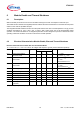
7 Module Oscillator
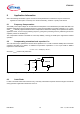
7.1 Description
The oscillator turns on the power switch with a constant frequency while the buck regulating circuit turns the power
transistor off in every cycle with an appropriate time gap depending on the output and input voltage.
The internal sawtooth signal used for the PWM generation has an amplitude proportional to the input supply
voltage (feedforward).
The turn-on frequency can optionally be set externally via the ’SYNC’ pin using a TTL compatible input signal. In
this case the synchronization of the PWM-on signal refers to the falling edge of the ’SYNC’-pin input signal. In case
the synchronization to an external clock signal is not needed the ’SYNC’ pin should be connected to GND.
Leaving pin SYNC open or short-circuiting it to GND leads to normal operation with the internal switching
frequency.
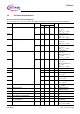
7.2 Electrical Characteristics Module Oscillator
Electrical Characteristics: Buck Regulator
V
S
= 6.0 V to 40 V, T
j
= -40 °C to +125°C, all voltages with respect to ground (unless otherwise specified)
Pos. Parameter Symbol Limit Values Unit Conditions
Min. Typ. Max.
7.2.1 Oscillator frequency
f
osc
330 370 420 kHz V
SYNC
= 0V
7.2.2 Synchronization capture range
f
sync
200 530 kHz
7.2.3 SYNC signal high level valid
V
SYNC,hi
2.9 V
1)
1) Synchronization of PWM-on signal to falling edge.
7.2.4 SYNC signal low level valid V
SYNC,lo
0.8 V
1)
7.2.5 SYNC input internal pull-down R
SYNC
0.60 1.0 1.4 MΩ V
SYNC
= 5V