
Datasheet


Data Sheet 16 Rev. 1.01, 2010-07-02
IFX8117
Application Hints
6 Application Hints
6.1 External Components
Input Capacitor
An input capacitor is recommended to compensate line influences. As a minimum a 100 nF ceramic input
capacitor should be used to filter high frequency noise. For buffering line transients a capacitance of 10µF is
suggested.
Output Capacitor
The output capacitor is part of the regulation loop of the regulator and therefore important to maintain stability. It
must meet the required conditions for minimum capacitance value and maximum value of equivalent series
resistance (ESR) as given in “Functional Range” on Page 8. An increase of the output capacitance will improve
the transient response and the loop stability. To achieve low voltage drops at load transients, tantalum capacitors
are recommended.
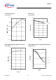
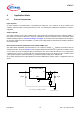
External Resistor Divider (Adjustable Version IFX8117MEV only)
The IFX8117MEV adjustable version develops a 1.25 V reference voltage,
V
Ref
, between the output Q and the
adjust terminal ADJ. As shown in Figure 6, this voltage is applied across resistor
R
1
to generate a constant current
I
1
. The current I
ADJ
from the adjust terminal could introduce error to the output. But since it is very small (50µA)
compared to the
I
1
and very constant with line and load changes, the error can be ignored. The constant current
I
1
then flows through the output set resistor R
2
and sets the output voltage to the desired level.
At the fixed voltage devices IFX8117MEV33 and IFX8117MEV50 the resistor divider is integrated inside the
device.
Figure 6 IFX8117MEV Adjustable Version
IFX 8117 MEV
Adjustable _Version .vsd
10 µF
10 µF
V
Q
= V
Ref
(1 + R
2
/R
1
) + I
ADJ
R
2
V
I
V
Q
ADJ
R
1
R
2
I
ADJ
I
1
V
Ref