
Datasheet

IFX 1117
Data Sheet 9 Rev. 1.0, 2011-02-24
Output
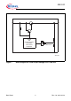
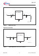
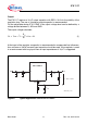
The IFX1117 requires a 10 μF outpu
t capacitor with ESR ≤ 20 Ω for the stability of the
regulation loop. The use of a tantalum output capacitor is recommended.
For the adjustable device IFX1117ME V the output voltage level can be defined by a
voltag
e divider between Q, ADJ and GND.
The output voltage calculates:
V
Q
V
REF
1
R
2
R
1
------+
⎝⎠
⎛⎞
× I
ADJ
R
2
×+=
(1)
At the input of the regulator a capacitor is recommended to compensate line influences.
As a minimum a 100 nF ceramic input capacitor should be used. If the regulator is used
in an environment with long input lines an input capacitance of 10 μF is suggested.
AES02815_1117
C
I
1
C
I
2
V
I
I
C
Q2
V
Q
Q
ADJ
R
2
C
ADJ
R
1
IFX1117ME V
V
Q
- V
ADJ
= V
REF
3 2
1
I
ADJ
Figure 6 Typical Application Circuit IFX1117ME V