
Datasheet

Data Sheet 8 Rev. 1.0, 2009-05-14
IFX1050G
Electrical Characteristics
6 Electrical Characteristics
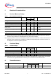
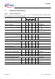
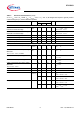
Table 3 Electrical Characteristics
4.5 V <
V
CC
< 5.5 V; R
L
= 60 Ω; V
INH
< V
INH,ON
; -40 °C < T
j
< 125 °C; all voltages with respect to ground; positive
current flowing into pin; unless otherwise specified.
Parameter Symbol Limit Values Unit Remarks
Min. Typ. Max.
Current Consumption
Current consumption
I
CC
– 6 10 mA Recessive state;
V
TxD
= V
CC
Current consumption I
CC
– 45 70 mA Dominant state;
V
TxD
= 0 V
Current consumption
I
CC
– 6 10 mA Receive - Only Mode;
RM = “LOW”
Current consumption
I
CC,stb
–110µA Stand - By Mode;
TxD = RM = “High”
Receiver Output RxD
HIGH level output current
I
RD,H
– -4-2mAV
RD
= 0.8 × V
CC
,
V
diff
< 0.4 V
1)
LOW level output current I
RD,L
24–mAV
RD
= 0.2 × V
CC
,
V
diff
> 1 V
1)
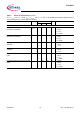
Transmission Input TxD
HIGH level input voltage threshold
V
TD,H
–0.5 ×
V
CC
0.7 ×
V
CC
V Recessive state
LOW level input voltage threshold
V
TD,L
0.3 ×
V
CC
0.4 ×
V
CC
– V Dominant state
TxD pull-up resistance
R
TD
10 25 50 kΩ –
Inhibit Input (pin INH)
HIGH level input voltage threshold
V
INH,H
–0.5 ×
V
CC
0.7 ×
V
CC
V Stand - By Mode;
LOW level input voltage threshold
V
INH,L
0.3 ×
V
CC
0.4 ×
V
CC
– V Normal Mode
INH pull-up resistance
R
INH
10 25 50 kΩ –
Receive only Input (pin RM)
HIGH level input voltage threshold
V
RM,H
–0.5 ×
V
CC
0.7 ×
V
CC
V Normal Mode
LOW level input voltage threshold
V
RM,L
0.3 ×
V
CC
0.4 ×
V
CC
– V Receive - Only Mode
RM pull-up resistance
R
RM
10 25 50 kΩ –