
Datasheet
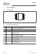

IFX1050G
Electrical Characteristics
Data Sheet 7 Rev. 1.0, 2009-05-14
5 Electrical Characteristics
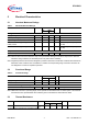
5.1 Absolute Maximum Ratings
Note: Stresses above the ones listed here may cause permanent damage to the device. Exposure to absolute
maximum rating conditions for extended periods may affect device reliability.
Note: Integrated protection functions are designed to prevent IC destruction under fault conditions described in the
data sheet. Fault conditions are considered as “outside” normal operating range. Protection functions are
not designed for continuous repetitive operation.
5.2 Functional Range
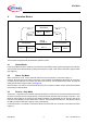
Note: Within the functional or operating range, the IC operates as described in the circuit description. The electrical
characteristics are specified within the conditions given in the Electrical Characteristics table.
5.3 Thermal Resistance
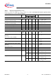
Table 1 Absolute Maximum Ratings
Parameter Symbol Limit Values Unit Remarks
Min. Max.
Voltages
Supply voltage
V
CC
-0.3 6.5 V –
CAN input voltage (CANH, CANL)
V
CANH/L
-40 40 V –
Logic voltages at INH, RM, TxD, RxD
V
I
-0.3 V
CC
V0 V < V
CC
< 5.5 V
Electrostatic discharge voltage at
CANH, CANL
V
ESD
-6 6 kV human body model (100 pF via
1.5 kΩ)
Electrostatic discharge voltage
V
ESD
-2 2 kV human body model (100 pF via
1.5 kΩ)
Temperatures
Junction temperature
T
j
-40 160 °C–
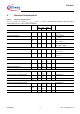
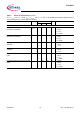
Table 2 Functional Range
Parameter Symbol Limit Values Unit Remarks
Min. Max.
Supply voltage
V
CC
4.5 5.5 V –
Junction temperature
T
j
-40 125 °C–
Thermal Shutdown (junction temperature)
Thermal shutdown temperature
T
jsD
160 200 °C 10 °C hysteresis
Pos. Parameter Symbol Limit Values Unit Conditions
Min. Typ. Max.
5.3.1 Junction to Ambient
1)
1) Not subject to production test, specified by design.
R
thJA
––185K/W