
Datasheet

CoolSET
®
-F3R
ICE3Bxx65J
Version 2.7 9 9 May 2012
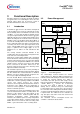
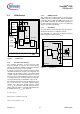
3.4 PWM Section
Figure 6 PWM Section
3.4.1 Oscillator and Jittering
The oscillator generates a fixed frequency with
frequency jittering of ±4% from the fixed frequency
(which is ±2.7kHz from 67kHz) at a jittering period T
FJ
.
The switching frequency is f
switch
= 67kHz.
A resistor, a capacitor and a current source and current
sink which determine the frequency are integrated. The
charging and discharging current of the implemented
oscillator capacitor are internally trimmed, in order to
achieve a very accurate switching frequency. The ratio
of controlled charge to discharge current is adjusted to
reach a maximum duty cycle limitation of D
max
=0.75.
Once the Soft Start period is over and when the IC goes
into normal mode, the Soft Start capacitor will be
charged and discharged through internal current
source, I
FJ
to generate a triangular waveform with a
jittering period T
FJ
which is externally adjustable by the
Soft Start capacitor, C
SoftS
(See Figure 4).
T
FJ
= k
FJ
* C
SoftS
where k
FJ
is a constant = 4 ms/uF
eg. T
FJ
= 4 ms if C
SoftS
= 1uF
3.4.2 PWM-Latch FF1
The oscillator clock output provides a set pulse to the
PWM-Latch when initiating the internal CoolMOS
®
conduction. After setting the PWM-Latch can be reset
by the PWM comparator, the Soft Start comparator or
the Current-Limit comparator. In case of resetting the
driver is shut down immediately.
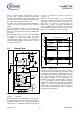
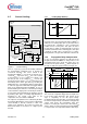
3.4.3 Gate Driver
The Gate Driver is a fast totem pole gate drive which is
designed to avoid cross conduction currents.
The Gate Driver is active low at voltages below the
undervoltage lockout threshold V
VCCoff
.
Figure 7 Gate Driver
Oscillator
Duty
Cycle
max
Gate Driver
0.75
Clock
&
G9
1
G8
PWM Section
FF1
R
S
Q
Gate
Soft Start
Comparator
PWM
Comparator
Current
Limiting
Frequency
Jitter
SoftS
VCC
1
PWM-Latch
Depl. CoolMOS™
Gate Driver
Gate