
Datasheet

CoolSET
®
-F3R
ICE3Bxx65J
Version 2.7 8 9 May 2012
When V
VCC
falls below the off-threshold V
CCoff
=10.3V
the bias circuit is switched off and the Power Down
reset let T1 discharging the soft-start capacitor C
SoftS
at
pin SoftS. Thus it is ensured that at every startup cycle
the voltage ramp at pin SoftS starts at zero.
The bias circuit is switched off if Auto Restart Mode is
entered. The current consumption is then reduced to
300uA.
Once the malfunction condition is removed, this block
will then turn back on. The recovery from Auto Restart
Mode does not require disconnecting the SMPS from
the AC line.
When Active Burst Mode is entered, some internal Bias
is switched off in order to reduce the current
consumption to about 500uA while keeping a
comparator (which trigger if V
FB
has exceeded 3.61V)
and the Soft Start capacitor clamped at 3.0 V as this is
necessary in this mode.
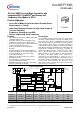
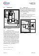
3.3 Startup Phase
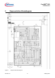
Figure 4 Soft Start
At the beginning of the Startup Phase, the IC provides
a Soft Start duration whereby it controls the maximum
primary current by means of a duty cycle limitation. A
capacitor C
Softs
in combination with the internal pull up
resistor R
SoftS
determines the duty cycle until V
SoftS
exceeds 3.1V.
When the Soft Start begins, C
SoftS
is immediately
charged up to approx. 0.8V by T2. Therefore the Soft
Start Phase takes place between 0.8V and 3.1V.
Above V
SoftsS
= 3.1V there is no longer duty cycle
limitation DC
max
which is controlled by comparator C7
since comparator C2 blocks the gate G7 (see Figure
5).This maximum charge current in the very first stage
when V
SoftS
is below 0.8V, is limited to 0.9mA.
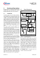
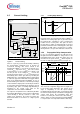
Figure 5 Startup Phase
By means of this extra charge stage, there is no delay
in the beginning of the Startup Phase when there is still
no switching. Furthermore Soft Start is finished at 3.1V
to have faster the maximum power capability. The duty
cycles DC
1
and DC
2
are depending on the mains and
the primary inductance of the transformer. The
limitation of the primary current by DC
2
is related to
V
SoftS
= 3.1V. But DC
1
is related to a maximum primary
current which is limited by the internal Current Limiting
with CS = 1V. Therefore the maximum Startup Phase
is divided into a Soft Start Phase until t1 and a phase
from t1 until t2 where maximum power is provided if
demanded by the FB signal.
Soft-Start
Comparator
Soft Start
&
G7
C7
C
SoftS
R
SoftS
T2
3.25k
5V
T3
0.8V
SoftS
Gate Driver
0.6V
x3.2
PWM OP
CS
3.1V
C2
Freq Jitter
Charging
current I
FJ
Freq Jitter
Discharging
current I
FJ
Freq Jitter
Control
DC
max
DC
1
DC
2
t
t
V
SoftS
max. Soft Start Phase
0.8V
3.1V
4.0V
max. Startup Phase
t1 t2