
Datasheet

Version 2.7 5 9 May 2012
CoolSET
®
-F3R
ICE3Bxx65J
1 Pin Configuration and Functionality
1.1 Pin Configuration with PG-DIP-8
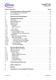
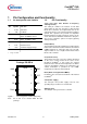
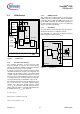
Figure 1 Pin Configuration PG-DIP-8(top view)
Note: Pin 4 and 5 are shorted within the DIP
package.
1.2 Pin Functionality
SoftS (Soft Start, Auto Restart & Frequency
Jittering Control)
The SoftS pin combines the function of Soft Start
during Start Up and error detection for Auto Restart
Mode. These functions are implemented and can be
adjusted by means of an external capacitor at SoftS to
ground. This capacitor also provides an adjustable
blanking window for high load jumps, before the IC
enters into Auto Restart Mode. Furthermore this pin is
also used to control the period of frequency jittering
during normal load.
FB (Feedback)
The information about the regulation is provided by the
FB Pin to the internal Protection Unit and to the internal
PWM-Comparator to control the duty cycle. The FB-
Signal controls in case of light load the Active Burst
Mode of the controller.
CS (Current Sense)
The Current Sense pin senses the voltage developed
on the series resistor inserted in the source of the
integrated CoolMOS
®
. If CS reaches the internal
threshold of the Current Limit Comparator, the Driver
output is immediately switched off. Furthermore the
current information is provided for the PWM-
Comparator to realize the Current Mode.
Drain (Drain of integrated CoolMOS
®
)
Pin Drain is the connection to the Drain of the internal
CoolMOS
TM
.
VCC (Power supply)
The VCC pin is the positive supply of the IC. The
operating range is between 10.3V and 26V.
GND (Ground)
The GND pin is the ground of the controller.
Pin Symbol Function
1 SoftS Soft-Start
2 FB Feedback
3 CS Current Sense/
650V
1)
CoolMOS
®
Source
4 Drain
650V
1)
CoolMOS
®
Drain
1)
at T
j
= 110°C
5 Drain
650V
1)
CoolMOS
®
Drain
6 N.C. Not Connected
7 VCC Controller Supply Voltage
8 GND Controller Ground
Package PG-DIP-8
1
6
7
8
4
3
2
5
GNDSoftS
FB
CS
VCC
N.C
Drain Drain