
Datasheet


Version 2.7 16 9 May 2012
CoolSET
®
-F3R
ICE3Bxx65J
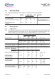
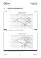
4.2 Operating Range
Note: Within the operating range the IC operates as described in the functional description.
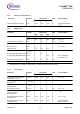
4.3 Characteristics
4.3.1 Supply Section
Note: The electrical characteristics involve the spread of values guaranteed within the specified supply voltage
and junction temperature range T
J
from – 25
o
C to 130
o
C. Typical values represent the median values,
which are related to 25°C. If not otherwise stated, a supply voltage of V
CC
= 18 V is assumed.
Parameter Symbol Limit Values Unit Remarks
min. max.
VCC Supply Voltage V
VCC
V
VCCoff
26 V
Junction Temperature of Controller T
jCon
-25 130 °C Max value limited due to
integrated thermal shut down
Junction Temperature of
CoolMOS
®
T
JCoolMOS
-25 150 °C
Parameter Symbol Limit Values Unit Test Condition
min. typ. max.
Start Up Current I
VCCstart
- 300 450 mA V
VCC
= 17V
VCC Charge Current I
VCCcharge1
- - 5.0 mA V
VCC
= 0V
I
VCCcharge2
0.55 1.05 1.60 mA V
VCC
= 1V
I
VCCcharge3
- 0.88 - mA V
VCC
= 17V
Leakage Current of
Start Up Cell & CoolMOS
I
StartLeak
- 0.2 50 mA V
Drain
= 450V
at T
j
= 100°C
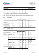
Supply
Current with
Inactive Gate
ICE3B0365J
ICE3B0565J
ICE3B1565J
I
VCCsup_ng1
- 1.7 2.5 mA Soft Start pin is open
ICE3B2065J I
VCCsup_ng2
- 3.3 4.2 mA
Supply Current with Active Gate I
VCCsup_g
- 2.5 3.6 mA V
SoftS
= 3.0V
I
FB
= 0
Supply Current in
Auto Restart Mode
with Inactive Gate
I
VCCrestart
- 300 - mA I
FB
= 0
I
Softs
= 0
Supply Current in
Active Burst Mode
with Inactive Gate
I
VCCburst1
- 500 950 uA V
FB
= 2.5V
V
SoftS
= 3.0V
I
VCCburst2
- 500 950 uA V
VCC
= 11.5V
V
FB
= 2.5V
V
SoftS
= 3.0V
VCC Turn-On Threshold
VCC Turn-Off Threshold
VCC Turn-On/Off Hysteresis
V
VCCon
V
VCCoff
V
VCChys
17.0
9.6
-
18.0
10.3
7.7
19.0
11.0
-
V
V
V