
Datasheet


CoolSET
®
-F3R
ICE3Bxx65J
Version 2.7 15 9 May 2012
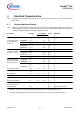
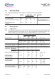
4 Electrical Characteristics
Note: All voltages are measured with respect to ground (Pin 8). The voltage levels are valid if other ratings are
not violated.
4.1 Absolute Maximum Ratings
Note: Absolute maximum ratings are defined as ratings, which when being exceeded may lead to destruction
of the integrated circuit. For the same reason make sure, that any capacitor that will be connected to pin 7
(VCC) is discharged before assembling the application circuit.
Parameter Symbol Limit Values Unit Remarks
min. max.
Drain Source Voltage V
DS
- 650 V T
j
= 110°C
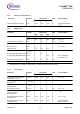
Pulse drain current,
t
p
limited by max.
T
j
=150°C
ICE3B0365J I
D_Puls1
- 1.6 A
ICE3B0565J I
D_Puls2
- 2.3 A
ICE3B1565J I
D_Puls3
- 6.1 A
ICE3B2065J I
D_Puls4
- 10.3 A
Avalanche energy,
repetitive t
AR
limited
by max. T
j
=150°C
1)
1)
Repetetive avalanche causes additional power losses that can be calculated as P
AV
=E
AR
* f
ICE3B0365J E
AR1
- 0.005 mJ
ICE3B0565J E
AR2
- 0.01 mJ
ICE3B1565J E
AR3
- 0.15 mJ
ICE3B2065J E
AR4
- 0.4 mJ
Avalanche current,
repetitive t
AR
limited
by max. T
j
=150°C
1)
ICE3B0365J I
AR1
- 0.3 A
ICE3B0565J I
AR2
- 0.5 A
ICE3B1565J I
AR3
- 1.5 A
ICE3B2065J I
AR4
- 2.0 A
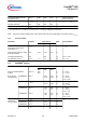
VCC Supply Voltage V
VCC
-0.3 27 V
FB Voltage V
FB
-0.3 5.0 V
SoftS Voltage V
SoftS
-0.3 5.0 V
CS Voltage V
CS
-0.3 5.0 V
Junction Temperature T
j
-40 150 °C Controller & CoolMOS
®
Storage Temperature T
S
-55 150 °C
Thermal Resistance
Junction-Ambient
R
thJA
- 90 K/W PG-DIP-8
ESD Capability V
ESD
- 2 kV Human body model
2)
2)
According to EIA/JESD22-A114-B (discharging a 100pF capacitor through a 1.5kW series resistor)