
Datasheet


CoolSET
®
-F3R
ICE3Bxx65J
Version 2.7 13 9 May 2012
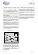
blocks C12 by the gate G10. Maximum current can now
be provided to stabilize V
OUT
.
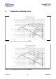
Figure 15 Signals in Active Burst Mode
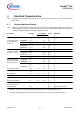
3.6.3 Protection Modes
The IC provides several protection features that
increase the SMPS system’s robustness and safety.
The following table shows the possible system failures
and the corresponding protection modes.
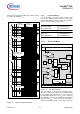
3.6.3.1 Auto Restart Mode I
Figure 16 Auto Restart Mode I
The VCC voltage is observed by comparator C13 if
20.5V is exceeded. The output of C13 is combined with
both the output of C3 which checks for V
SoftS
< 4.0V and
the output of C4 which checks for V
FB
> 4.5V. Therefore
the overvoltage detection can only be active during Soft
Start Phase (V
SoftS
< 4.0V) and when FB signal is
outside the operating range > 4.5V. This means any
1.35V
3.61V
4.5V
V
FB
3.0V
4.0V
V
SoftS
t
t
0.32V
1.0V
V
CS
10.3V
V
VCC
t
t
500uA
I
VCC
t
2mA
V
OUT
t
Max. Ripple < 1%
Blanking Window
Current limit level
during Active Burst
Mode
3.0V
Entering
Active Burst
Mode
Leaving
Active Burst
Mode
3.6V~
3.2V
VCC Overvoltage Auto Restart Mode I
Over temperature Auto Restart Mode I
Overload Auto Restart Mode II
Open Loop Auto Restart Mode II
VCC Undervoltage Auto Restart Mode II
Short Optocoupler Auto Restart Mode II
C3
Spike
Blanking
8.0us
Thermal Shutdown
T
j
>140°C
Auto
Restart
Mode
Internal
Bias
Control Unit
C13
20.5V
VCC
C4
4.5V
FB
4.0V
SoftS
&
G12
&
G13
FF2
R
S
Q
UVLO