
Datasheet
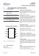

CCM-PFC
ICE2PCS01/G
Functional Description
Version 2.3 8 22 March 2010
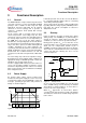
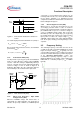
Figure 5 Startup with controlled maximum current
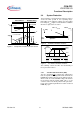
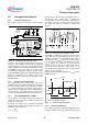
3.4 System Protection
The IC provides several protection features in order to
ensure the PFC system in safe operating range.
Depending on the input line voltage (V
IN
) and output
bus voltage (V
OUT
), Figure 7 and 8 show the conditions
when these protections are active.
Figure 6 V
IN
Related Protection Features
Figure 7 V
OUT
Related Protection Features
The following sections describe the functionality of
these protection features.
3.4.1 Soft Over Current Control (SOC)
The IC is designed not to support any output power
that corresponds to a voltage lower than -0.75V at the
ISENSE pin. A further increase in the inductor current,
which results in a lower ISENSE voltage, will activate
the Soft Over Current Control (SOC). This is a soft
control as it does not directly switch off the gate drive.
It acts on the nonlinear gain block to result in a reduced
PWM duty cycle.
av(I
IN
)
V
OUT
t
V
OUT
=rated
95%rated
Window Detect
Normal Control
t
Max Vcomp current
83%rated
VCOMP
Level-shifted VCOMP
t
V
IN
(VAC)
VCC > V
CCUVLO
Normal
Operation
IC OFF
VCC<V
CCUVLO
IC’s
State
t
V
OUT
PCL / SOC
20%
100%
OLP OLP
108%
OVP
V
OUT,Rated