
Datasheet

CCM-PFC
ICE2PCS01/G
Electrical Characteristics
Version 2.3 16 22 March 2010
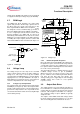
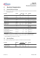
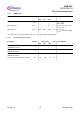
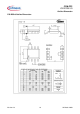
4.3.5 Current Loop Section
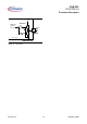
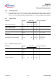
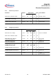
4.3.6 Voltage Loop Section
Parameter Symbol Limit Values Unit Test Condition
min. typ. max.
OTA2 Transconductance Gain Gm
OTA2
0.8 1.0 1.3 mS At Temp = 25°C
OTA2 Output Linear Range
1)
I
OTA2
- ± 50 - mA
ICOMP Voltage during OLP V
ICOMPF
3.9 4.2 - V V
VSENSE
= 0.5V
Parameter Symbol Limit Values Unit Test Condition
min. typ. max.
OTA1 Reference Voltage V
OTA1
2.92 3.00 3.08 V measured at VSENSE
OTA1 Transconductance Gain Gm
OTA1
26 39 51 mS
OTA1 Max. Source Current
Under Normal Operation
I
OTA1SO
18 30 38 mA V
VSENSE
= 2V
V
VCOMP
= 3V
OTA1 Max. Sink Current
Under Normal Operation
I
OTA1SK
21 30 41 mA V
VSENSE
= 4V
V
VCOMP
= 3V
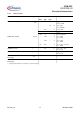
Enhanced Dynamic Response
VSENSE High Threshold
VSENSE Low Threshold
V
Hi
V
Lo
3.09
2.76
3.18
2.85
3.26
2.94
V
V
VSENSE Input Bias Current at 3V I
VSEN3V
0 - 1.5 mA V
VSENSE
= 3V
VSENSE Input Bias Current at 1V I
VSEN1V
0 - 1 mA V
VSENSE
= 1V
VCOMP Voltage during OLP V
VCOMPF
0 0.2 0.4 V V
VSENSE
= 0.5V
I
VCOMP
= 0.5mA