
Datasheet

CCM-PFC
ICE2PCS01/G
Electrical Characteristics
Version 2.3 14 22 March 2010
4.3 Characteristics
Note: The electrical characteristics involve the spread of values within the specified supply voltage and junction
temperature range T
J
from – 40 °C to 125°C.Typical values represent the median values, which are
related to 25°C. If not otherwise stated, a supply voltage of V
CC
=18V is assumed for test condition.
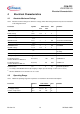
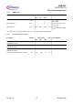
4.3.1 Supply Section
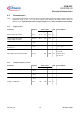
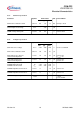
4.3.2 Variable Frequency Section
Parameter Symbol Limit Values Unit Test Condition
min. typ. max.
VCC Turn-On Threshold V
CCon
11.4 11.8 12.7 V
VCC Turn-Off Threshold/
Under Voltage Lock Out
V
CCUVLO
10.4 11.0 11.7 V
VCC Turn-On/Off Hysteresis V
CChy
0.65 0.8 1.4 V
Start Up Current
Before V
CCon
I
CCstart
- 450 1100 mA V
VCC
=V
VCCon
-0.1V
Operating Current with active GATE I
CCHG
- 15 20 mA R5 = 33kW
C
L
= 4.7nF
Operating Current during Standby I
CCStdby
- 700 1300 mA V
VSENSE
= 0.5V
V
ICOMP
= 4V
Parameter Symbol Limit Values Unit Test Condition
min. typ. max.
Switching Frequency (Typical) F
SWnom
124 136 147 kHz R5 = 33kW
Switching Frequency (Min.) F
SWmin
50 56 62 kHz R5 = 82kW
Switching Frequency (Max.) F
SWmax
250 285 315 kHz R5 = 15kW
Voltage at FREQ pin V
FREQ
1.65 1.70 1.76 V