
Datasheet

CCM-PFC
ICE2PCS01/G
Electrical Characteristics
Version 2.3 13 22 March 2010
4 Electrical Characteristics
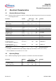
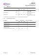
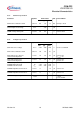
4.1 Absolute Maximum Ratings
Note: Absolute maximum ratings are defined as ratings, which when being exceeded may lead to destruction
of the integrated circuit.
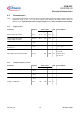
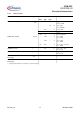
4.2 Operating Range
Note: Within the operating range the IC operates as described in the functional description.
Parameter Symbol Limit Values Unit Remarks
min. max.
V
CC
Supply Voltage V
CC
-0.3 25 V
FREQ Voltage V
FREQ
-0.3 5 V
ICOMP Voltage V
ICOMP
-0.3 5 V
ISENSE Voltage V
ISENSE
-20 5 V
2)
ISENSE Current I
ISENSE
-1 1 mA Recommended R2=220W
VSENSE Voltage V
VSENSE
-0.3 5 V
VSENSE Current I
VSENSE
-1 1 mA R3>400kW
VCOMP Voltage V
VCOMP
-0.3 5 V
GATE Voltage V
GATE
-0.3 17 V Clamped at 15V if driven
internally.
Junction Temperature T
j
-40 150 °C
Storage Temperature T
S
-55 150 °C
Thermal Resistance
Junction-Ambient for DSO-8-13
R
thJA
(DSO) - 185 K/W PG-DSO-8-13
Thermal Resistance
Junction-Ambient for DIP-8-4
R
thJA
(DIP) - 90 K/W PG-DIP-8-4
ESD Protection V
ESD
- 2 kV Human Body Model
1)
1)
According to EIA/JESD22-A114-B (discharging a 100pF capacitor through a 1.5kW series resistor)
2)
Absolute ISENSE current should not be exceeded
Parameter Symbol Limit Values Unit Remarks
min. max.
V
CC
Supply Voltage V
CC
V
CCUVLO
25 V
Junction Temperature T
JCon
-40 125 °C