
Datasheet

Data Sheet 5 V1.0, 2007-05-13
Smart High-Side Power Switch
BTS740S2
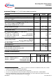
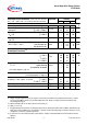
Parameter and Conditions, each of the two channels Symbol Values Unit
at Tj = -40...+150°C,
V
bb
= 12 V unless otherwise specified
min typ max
Overvoltage hysteresis ∆
V
bb(over)
-- 1 -- V
Overvoltage protection
10)
T
j
=-40:
I
bb
=40 mA
T
j
=+25...+150°C:
V
bb(AZ)
41
43
--
47
--
52
V
Standby current
11
)
T
j
=-40°C...25°C:
V
IN
= 0;
T
j
=150°C:
I
bb(off)
--
--
8
24
30
50
µA
Leakage output current (included in
I
bb(off)
)
V
IN =0
I
L(off)
-- -- 20 µA
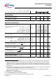
Operating current
12)
,
V
IN
= 5V,
I
GND
=
I
GND1
+
I
GND2
, one channel on:
two channels on:
I
GND
--
--
1.2
2.4
3
6
mA
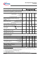
Protection Functions
13)
Current limit, (see timing diagrams, page 12)
T
j
=-40°C:
T
j
=25°C:
T
j
=+150°C:
I
L(lim)
48
40
31
56
50
37
65
58
45
A
Repetitive short circuit current limit,
T
j
=
T
jt
each channel
two parallel channels
(see timing diagrams, page 12)
I
L(SCr)
--
--
24
24
--
--
A
Initial short circuit shutdown time
T
j,start
=25°C:
(see timing diagrams on page 12)
t
off(SC)
-- 2.0 -- ms
Output clamp (inductive load switch off)
14)
at V
ON(CL)
= V
bb
- V
OUT
,
I
L
= 40 mA
T
j
=-40°C:
T
j
=25°C...150°C:
V
ON(CL)
41
43
--
47
--
52
V
Thermal overload trip temperature
T
jt
150 -- -- °C
Thermal hysteresis
∆
T
jt
-- 10 -- K
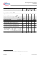
10)
Supply voltages higher than V
bb(AZ)
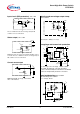
require an external current limit for the GND and status pins (a 150 Ω
resistor in the GND connection is recommended). See also
V
ON(CL)
in table of protection functions and
circuit diagram page 9.
11)
Measured with load; for the whole device; all channels off
12)
Add
I
ST
, if
I
ST
> 0
13
Integrated protection functions are designed to prevent IC destruction under fault conditions described in the
data sheet. Fault conditions are considered as "outside" normal operating range. Protection functions are no
t
designed for continuous repetitive operation.
14)
If channels are connected in parallel, output clamp is usually accomplished by the channel with the lowest
V
ON(CL)