
Datasheet
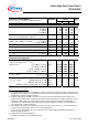

Parameter and Conditions Symbol Values Unit
a
t
T
j = 25 °C,
V
bb
= 12 V unless otherwise specified
min typ max
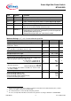
Operating Parameters
Operating voltage
5)
T
j
=-40...+150°C:
V
bb(on)
5.0 -- 34 V
Undervoltage shutdown
T
j
=-40...+150°C:
V
bb(under)
3.2 -- 5.0 V
Undervoltage restart
T
j
=-40...+25°C:
T
j
=+150°C:
V
bb(u rst)
-- 4.5 5.5
6.0
V
Undervoltage restart of charge pump
see diagram page 13
T
j
=-40...+25°C:
T
j
=25...150°C:
V
bb(ucp)
--
--
4.7
--
6.5
7.0
V
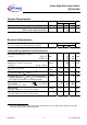
Undervoltage hysteresis
∆
V
bb(under)
=
V
bb(u rst)
-
V
bb(under)
∆
V
bb(under)
-- 0.5 -- V
Overvoltage shutdown
T
j
=-40...+150°C:
V
bb(over)
34 -- 43 V
Overvoltage restart
T
j
=-40...+150°C:
V
bb(o rst)
33 -- -- V
Overvoltage hysteresis
T
j
=-40...+150°C:
∆
V
bb(over)
-- 1 -- V
Overvoltage protection
6)
T
j
=-40°C:
I
bb
=40 mA
T
j
=+25...+150°C
V
bb(AZ)
41
43
--
47
--
52
V
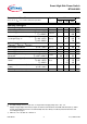
Standby current (pin 4)
V
IN
=0
T
j
=-40...+25°C:
T
j
= 150°C:
I
bb(off)
--
--
4
12
15
25
µA
Off state output current (included in
I
bb(off)
)
V
IN=0
,
T
j
=-40...+150°C
:
I
L(off)
-- -- 10 µA
Operating current (Pin 2)
7)
,
V
IN
=5 V
I
GND
-- 1.2 3 mA
5
)
At supply voltage increase up to
V
bb
= 4.7 V typ without charge pump,
V
OUT
≈
V
bb
- 2 V
6
)
Supply voltages higher than V
bb(AZ)
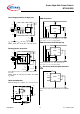
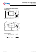
require an external current limit for the GND and status pins (a 150 Ω
resistor in the GND connection is recommended). See also
V
ON(CL)
in table of protection functions and
circuit diagram page 9.
7
)
Add
I
ST
, if
I
ST
> 0, add
I
IN
, if
V
IN
>5.5 V
Data Sheet 4 V1.1, 2008-19-08
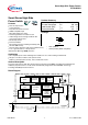
Smart High-Side Power Switch
BTS640S2G