
Data Sheet


PROFET
®
BTS 6133D
Data Sheet Page 2 of 17 Rev. 1.0, 2007-02
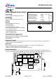
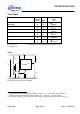
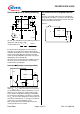
Pin Symbol Function
1 OUT O Output; output to the load; pin 1 and 5 must be externally
shorted* .
2 IN I Input; activates the power switch if shorted to ground.
Tab/(3) V
bb
+ Supply Voltage; positive power supply voltage; tab and pin3
are internally shorted.
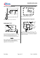
4 IS S Sense Output; Diagnostic feedback; provides at normal
operation a sense current proportional to the load current; in
case of overload, overtemperature and/or short circuit a
defined current is provided (see Truth Table on page 8)
5 OUT O Output; output to the load; pin 1 and 5 must be externally
shorted*.
*) Not shorting all outputs will considerably increase the on-state resistance, reduce the peak current capability
and decrease the current sense accuracy
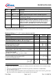
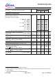
Maximum Ratings at Tj = 25 °C unless otherwise specified
Parameter Symbol Values Unit
Supply voltage (overvoltage protection see page 4) V
bb
38 V
Supply voltage for full short circuit protection
1)
V
bb
30 V
Load dump protection V
LoadDump
= U
A
+ V
s
, U
A
= 13.5 V
R
I
= 2 Ω, R
L
= 1.5 Ω, t
d
= 400 ms, IN= low or high
V
Load dump
2
)
45 V
Load current (Short-circuit current, see page 5) I
L
self-limited A
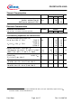
Operating temperature range
Storage temperature range
T
j
T
stg
-40 ...+150
-55 ...+150
°C
Power dissipation (DC) P
tot
59 W
Inductive load switch-off energy dissipation
3)
single pulse I
L
= 20 A, V
bb
= 12V T
j
=150 °C:
E
AS
0.3 J
Electrostatic discharge capability (ESD)
(Human Body Model)
acc. ESD assn. std. S5.1-1993; R=1.5kΩ; C=100pF
V
ESD
3.0
kV
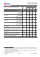
Current through input pin (DC)
Current through current sense pin (DC)
see internal circuit diagrams page 9
I
IN
I
IS
+15, -120
+15, -120
mA
Input voltage slew rate
V
bb
≤ 16V :
V
bb
> 16V
4)
:
dV
bIN
/ dt
self-limited
20
V/µs
1)
Short circuit is defined as a combination of remaining resistances and inductances. See schematic on page
11.
2)
V
Load dump
is setup without the DUT connected to the generator per ISO 7637-1 and DIN 40839.
3)
See also diagram on page 11.
4)
See also on page 8. Slew rate limitation can be achieved by means of using a series resistor R
IN
in the input
path. This resistor is also required for reverse operation. See also page 10.