
Data Sheet


PROFET
®
BTS 6133D
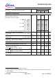
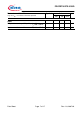
Data Sheet Page 10 of 17 Rev. 1.0, 2007-02
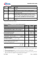
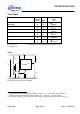
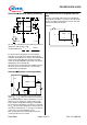
Reversave (Reverse battery protection)
Logic
IN
IS
R
OUT
L
R
Power GND
Signal GND
V
bb
-
Power
Transistor
IN
R
bb
R
D
R
IS
typ. 1 kΩ. Add R
IN
for reverse battery protection in
applications with V
bb
above 16V;
recommended value:
=+
ISIN
RR
11
VV
A
bb
12||
08.0
−
To minimise power dissipation at reverse battery
operation, the overall current into the IN and IS pin
should be about 80mA. The current can be provided by
using a small signal diode D in parallel to the input
switch, by using a MOSFET input switch or by proper
adjusting the current through R
IS.
Since the current via R
bb
generates additional heat in
the device, this has to be taken into account in the
overall thermal consideration.
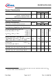
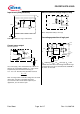
Inversave (Inverse current operation)
PROFET
V
IN
OUT
IS
bb
V
bb
V
OUT
- I
L
R
IS
V
IS
V
IN
+
-
+
-
I
IS
The device can be operated in inverse load current
mode (V
OUT
> V
bb
> 0V). The current sense feature is
not available during this kind of operation (I
IS
= I
IS(LH)
).
With I
IN
= 0 (e.g. input open) only the intrinsic drain
source diode is conducting resulting in considerably
increased power dissipation. If the device is switched
on (V
IN
= 0), the power dissipation is decreased to the
much lower value R
ON(INV)
* I
2
as long as a maximum
current I
L(inv)
is not exceeded(see on p4).
Note: Temperature protection during inverse load
current operation is not possible!
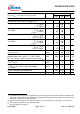
V
bb
disconnect with energised inductive
load
Provide a current path with load current capability by
using a diode, a Z-diode, or a varistor. (V
ZL
+V
D
<39 V if
R
IN
= 0). For higher clamp voltages currents at IN and
IS have to be limited to 120 mA.
Version a:
PROFET
V
IN
OUT
IS
bb
V
bb
V
ZL
V
D