
Datasheet

Data Sheet BTS50055-1TMC
Page 7 of 17 2010-April-27
Terms
PROFET
V
IN
IS
OUT
bb
V
IN
I
IS
I
IN
V
bb
I
bb
I
L
V
OUT
V
ON
3
5
4
1,2,6,7
R
IS
V
IS
V
bIN
R
IN
D
S
V
bIS
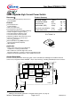
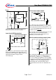
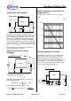
Two or more devices can easily be connected in
parallel to increase load current capability.
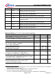
Input circuit (ESD protection)
IN
ZD
IN
I
V
bb
R
bb
V
Z,IN
V
bIN
V
IN
When the device is switched off (I
IN
= 0) the voltage
between IN and GND reaches almost V
bb
. Use a
mechanical switch, a bipolar or MOS transistor with
appropriate breakdown voltage as driver.
V
Z,IN
= 66 V (typ).
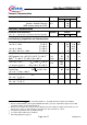
Current sense status output
IS
IS
R
IS
I
ZD
IS
V
bb
V
bb
R
Z,IS
V
V
Z,IS
= 66 V (typ.), R
IS
= 1 kΩ nominal (or 1 kΩ /n, if n
devices are connected in parallel). I
S
= I
L
/k
ilis
can be
driven only by the internal circuit as long as V
out
- V
IS
>
5 V. If you want measure load currents up to I
L(M)
, R
IS
should be less than
V
bb
- 5 V
I
L(M)
/ K
ilis
.
Note: For large values of R
IS
the voltage V
IS
can reach
almost V
bb
. See also overvoltage protection.
If you don't use the current sense output in your
application, you can leave it open.
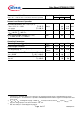
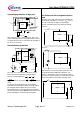
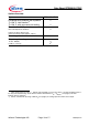
Inductive and overvoltage output clamp
+ V
bb
OUT
PROFET
V
Z1
V
ON
D
S
IS
V
OUT
V
ZG
V
ON
is clamped to V
ON(Cl)
= 42 V typ. At inductive load
switch-off without D
S
, V
OUT
is clamped to V
OUT(CL)
=
-19
V typ. via V
ZG
. With D
S
, V
OUT
is clamped to V
bb
-
V
ON(CL)
via V
Z1
. Using D
S
gives faster deenergizing of
the inductive load, but higher peak power dissipation in
the PROFET. In case of a floating ground with a
potential higher than 19V referring to the OUT –
potential the device will switch on, if diode DS is not
used.