
Datasheet


Datasheet 7 Rev. 1.1, 2008-02-28
Smart Low Side Power Switch
HITFET - BTS3160D
Pin Configuration
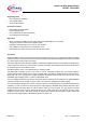
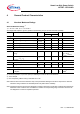
3 Pin Configuration
3.1 Pin Assignment BTS3160D
Drain
(top view)
GND
5
6 (Tab)
4
3
2
1
GND
IN / Fault
V
S
PinConfiguration.emf
Figure 3 Pin Configuration PG-TO-252-5-13
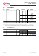
3.2 Pin Definitions and Functions
Pin Symbol Function
1 V
S
Supply Voltage; Connected to Battery Voltage with Reverse polarity protection
2 IN Control Input and Status Feedback; Digital input 3.3 V or 5 V logic.
3, Tab Drain Drain output; Protected low side power output channel
4,5 GND Ground; Signal ground, Pin 4 and 5 must be externally shorted
1) Not shorting pin 4 and 5 will considerably increase the on-state resistance and reduce the peak current capability.
1)