
Datasheet

Datasheet 27 Rev. 1.1, 2008-02-28
Smart Low Side Power Switch
HITFET - BTS3160D
Application Information
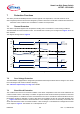
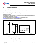
Conditions in formulas:
1. µCoutput current,min > µC
HIGH
,max / R
IN
> I
Fault_ONth
with µCoutput current,min referring to the micro controller maximum output current capability.
with µCHIGH,max referring to the maximal high output voltage of the micro controller driving stage.
This condition is valid during status feedback operation mode.
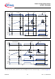
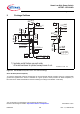
2. V
IN
= µC
HIGH
,min - (R
IN
* I
IN
,max) > V
INH
,min
with µCHIGH,min referring to the minimal high output voltage of the micro controller driving stage.
This condition is valid during normal operation mode
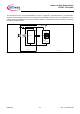
3. µC
HIGH
,max - (R
IN
* I
IN
-Fault,min) < µC(DI)L,max
with µC(DI)L,max referring to the maximum logic low voltage of the micro controller input stage
The maximum current is either defined by the BTS3160D or the micro controller driving stage
This condition is valid during status feedback operation mode
4. I
IN-Fault
= µC
HIGH,min
/ R
IN
> I
Fault_ONth
with µC
HIGH,min
referring to the minimum logic low voltage of the micro controller output stage
The BTS3160D is resetting the fault latch, if the current on IN pin goes below I
Fault_ONth.
This condition is valid during status feedback operation mode
Out of this conditions the minimum and maximum resistor values can be calculated.
For a typical 5V micro controller with output current capability in the 3 mA range,
a resistor range from 7.5 kΩ down to 4.5 kΩ can be used.
For a typical 3.3V micro controller a range from 4.6 kΩ to 2.5 kΩ is suitable.
We recommend 3k3 for a 3.3V µC and 5k6 for a 5V µC to achieve a logic low signal.
8.2 Further Application Information
• For further information you may contact http://www.infineon.com/hitfet