
Datasheet

Datasheet 26 Rev. 1.1, 2008-02-28
Smart Low Side Power Switch
HITFET - BTS3160D
Application Information
8 Application Information
Note: The following information is given as a hint for the implementation of the device only and shall not be
regarded as a description or warranty of a certain functionality, condition or quality of the device.
8.1 Dimensioning of serial Resistor at IN pin
In order to use the digital feedback function of the device, there is serial resistor necessary between the IN pin and
the driver (micro controller)
To calculate the value of this serial resistor on the input pin three device conditions as well as the driver (micro
controller) abilities needs to be taken into account.
The driver must be capable of driving at least IFault_ONth to avoid immediate restart
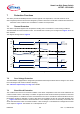
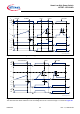
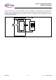
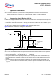
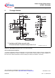
Figure 22 shows the circuit used for reading out the digital status.
Fault_RIN.emf
IN/Fault
DO
DI
I
DO
I
IN
R
IN
1.0mA
:
3.0mA
20µA
:
100µA
Fault information
Microcontroller
BTS3160D
V
RIN
GND
V
DO
V
DI
GND
V
CC
V
S
GND
V
CC
V
bb
Figure 22 Circuitry to readout fault information
Note: This is a very simplified example of an application circuit. The function must be verified in the real application.
Conditions to be meet by the circuitry:
• During normal operation V
IN
must be higher than V
INH,min
to switch ON.
• During fault condition the max. capability of the driver (micro controller) must not be exceeded and the logic
low level at DI must be ensured by a voltage drop over the serial resistor
R
IN
while the device fault current is
flowing.
• During fault state the device keeps protection active as long as it can sink more than the threshold current
I
Fault_ONth
. In case the device can not sink this current, it resets the protection and waits for the next input high
signal. So to avoid an unintentional switch ON/OFF behavior, the input current must be above this threshold.