
Datasheet

Datasheet 8 Rev. 3.1, 2013-02-21
BCR450
LED Driver IC
Electrical Characteristics
3.2 Digital Signals
All parameters are tested at 25 °C, unless otherwise specified
Table 6 Digital Control Parameter (EN)
Parameter Symbol Values Unit Note /
Te
st Condition
Min. Typ. Max.
PWM signal frequency
f
PWM
1000 Hz t
dutycycle
= 1%;
signal level
reaches 100% in
on and off mode
PWM Duty cycle
t
dutyPWM
5 % F = 5 kHz; signal
level reaches
100% in on and off
mode
PWM voltage
U
PWM
5 V
EN input capacitance to GND C
EN
130 pF EN = 0 V
3.3 Transient Parameters
8 V < V
S
< 27 V; - 40 °C < T
J
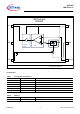
< 150 °C, all voltages with respect to ground; current directions as given in Figure 2;
unless otherwise specified
All parameters are tested at 25 °C, unless otherwise specified
Table 7 Digital Control Parameter (EN)
Parameter Symbol Values Unit Note / Test Condition
Min. Typ. Max.
Response Time
T
ON
10 μs EN: 0 -> 5 V @ t
rise
< 20 ns
t
risetime
@(10...90%) * V
sense
(
I
out
~ 15 mA);R
sense
= 10 Ω
T
OFF
70 μs EN: 5 V -> 0 @ t
fall
< 20 ns
t
falltime
@(90...10%) * V
sense
(
I
out
~ 15 mA); R
sense
= 10 Ω