
Datasheet

BCR450
LED Driver IC
Electrical Characteristics
Datasheet 7 Rev. 3.1, 2013-02-21
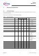
3 Electrical Characteristics
3.1 DC Characteristics
8 V < V
S
< 27 V; - 40 °C < T
J
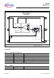
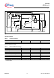
< 150 °C, all voltages with respect to ground; current directions as given in Figure 2;
unless otherwise specified
All parameters are tested at 25 °C, unless otherwise specified
Table 5 DC Characteristics
Parameter Symbol Values Unit Note / Test Condition
Min. Typ. Max.
Overall current consumption
Is
short
70 90 mA I
s
short; V
s
= 8..27 V
V
sense
= 20 mV
Overall current consumption
Is
short
600 μA I
s
short; V
s
= 42 V
V
sense
= 20 mV
Overall standby current consumption
Is
standby
200 nA EN = 0 V; V
s
= 8..27 V
V
sense
= 20 mV
Current of enable input
I
EN
20 40 70 μA V
sense
= 0..200 mV
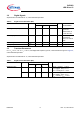
Current of driver output
I
outhigh
70 90 mA V
sense
= 20 mV;
V
s
= 8 V
Current of driver output
I
outlow
100 nA V
sense
= 200 mV;
V
s
= 8V
Current of Sense input
I
sense
200 nA V
sense
= 20..200 mV
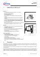
Voltage of Driver output
V
out
6 V I
out
= 15 mA;
S1, S6, S8, S9 = on;
R1 = 390 Ω;
R2 = 10 Ω;
see Figure 2
Voltage of Sense input
V
sense
135 150 165 mV I
out
= 15 mA;
V
s
= 8..27 V
S3, S6, S8
= on;
R1 = 390 Ω;R2 = 10 Ω
T
J
= 115 °C
see Figure 2
Enable voltage range
U
Pon
-0.3 5
1)
1) ESD protection diode of pin 3 (EN) will breakdown above 5 V input voltage to GND
V
Control voltage for power on
U
On
0.6 0.85 5 V
Control voltage for power off
U
Off
-0.3 0.35 V
Over voltage Protection
V
s, OV
27 V I
out
-> 0 A
Delta sense voltage Δ
V
sense
2 10 50 mV I
out
: 0 -> 50 mA
Drop Voltage
V
s
- V
out
1.2 V I
out
< 40 mA
Temperature shut down
T
SD
130 150 170 °C I
out
-> 0 A; refer to T
J